Lab 6
The lab deals with using PID control to correct orientation and turning in the RC car. A lot of the concepts are built on from the previous lab.
Prelab
This prelab is identical to the prelab from Lab 5. My method for sending and receiving data via Bluetooth is the same. I implemented additional helper functions in Arduino to help compute the orientation control separate from the linear control.
Orientation Control
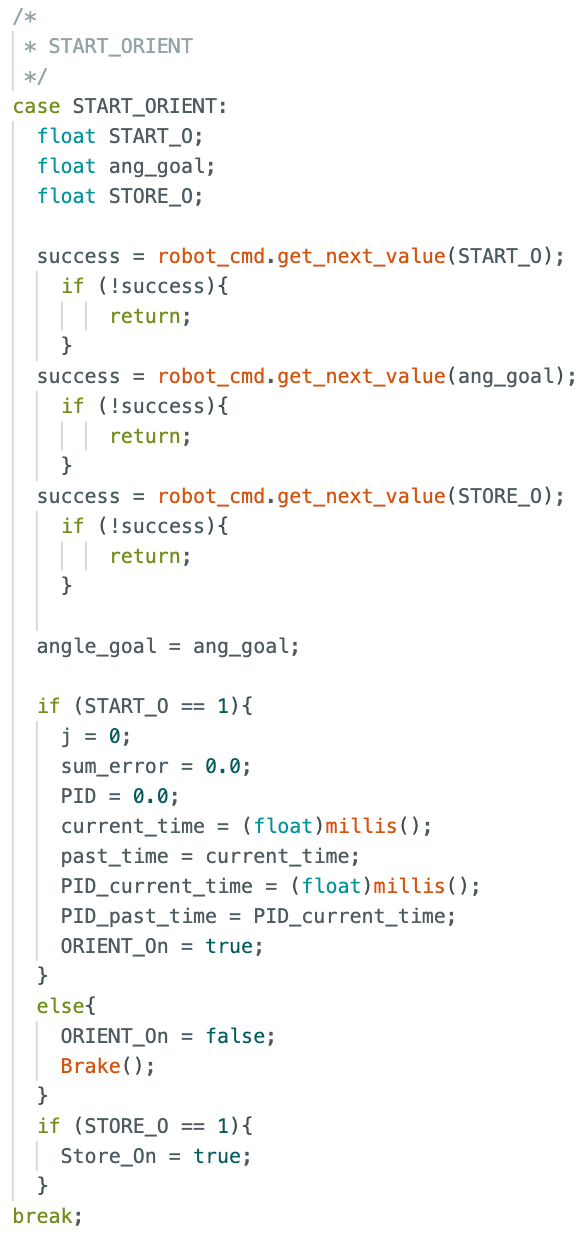
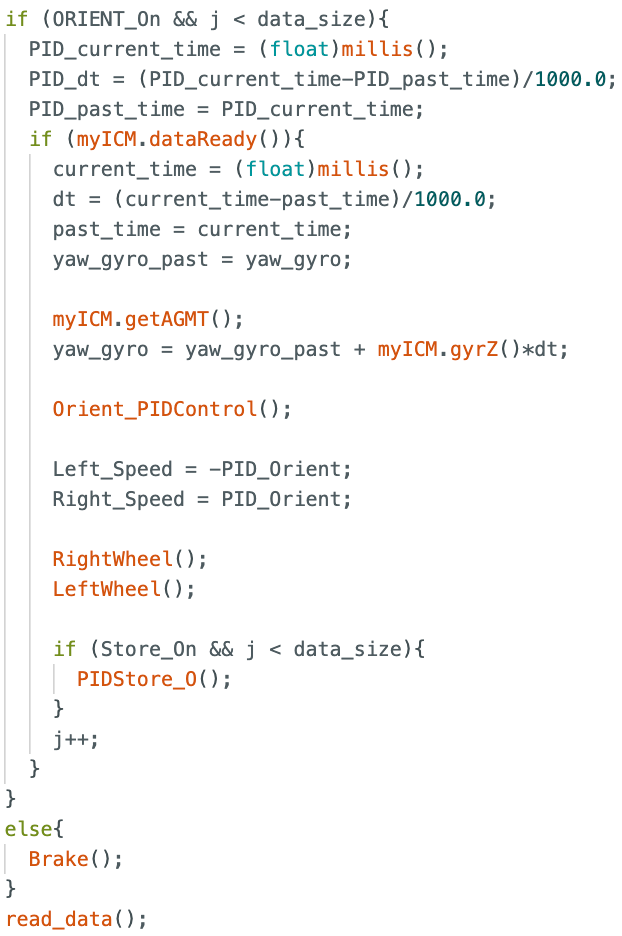
The goal of this lab is to have the RC car correct itself to a desired angle. By using PID control, the car can quickly reach its target goal as well as minimize steady state error and overshoot. Much like the linear control from Lab 5, this will be an iterative process. In order to gather orientation data of the RC car, we will use the onboard gyroscope on the IMU. This IMU was developed in lab 2, so much of the backend issues have already been dealt with. The basis of this lab will be to replace all TOF data collection with IMU yaw data, since yaw is the only rotational axis that we care about for spinning the RC car. Additionally, since we want the car to rotate instead of move forwards or backwards, the wheels will now be spinning in opposite directions. The portion of my main loop that deals with orientation as well as the case that turns on the flag to begin orientation PID control are shown below.
Sampling Frequency
The IMU is able to collect data at a much faster rate than the TOF sensors. Instead of 100 ms like in lab 5, we are able to gather new yaw data every 4 ms. This means the limiting factor is the PID control, rather than the sampling sensor.
PID Implementation
The first step is to guess an initial proportional gain (KP), and see how the RC car reacts. For my tests, I will be setting the target angle to 180 degrees, meaning we expect the RC car to be able to turn around and settle facing the opposite direction. After several trials, I found that a KP value of 4 was optimal. This allowed the car to settle within a second and had minimal oscillation issues. Regardless, these oscillations will be removed when the derivative control is implemented. A video of the P controller as well as the accompanying plot of angle, P, and PID over time are shown below.
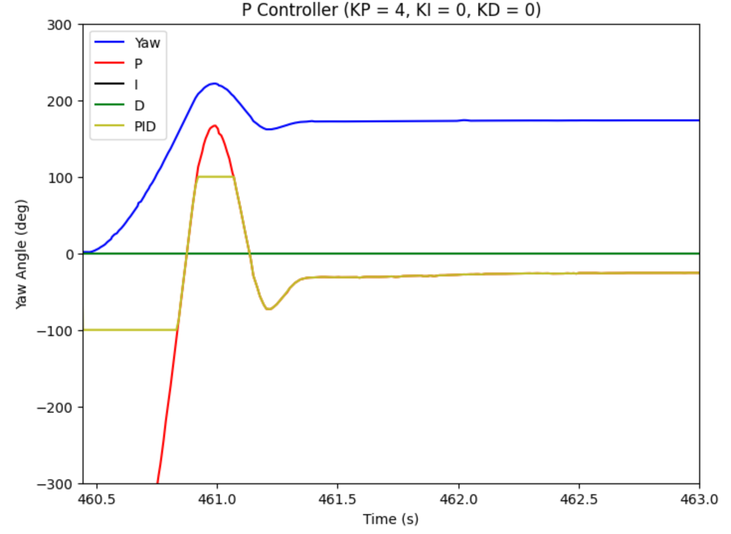
One issue that I started to run in to was that the minimum PWM value for rotation is much higher than that of linear movement. This means that I had to adjust the deadband threshold from 25 to 40. This increase of lower limit allowed the RC car to make finer angle adjustments as the error decreased and PWM value decreased. Otherwise, the wheels would not have enough power to rotate at such low PWM inputs.
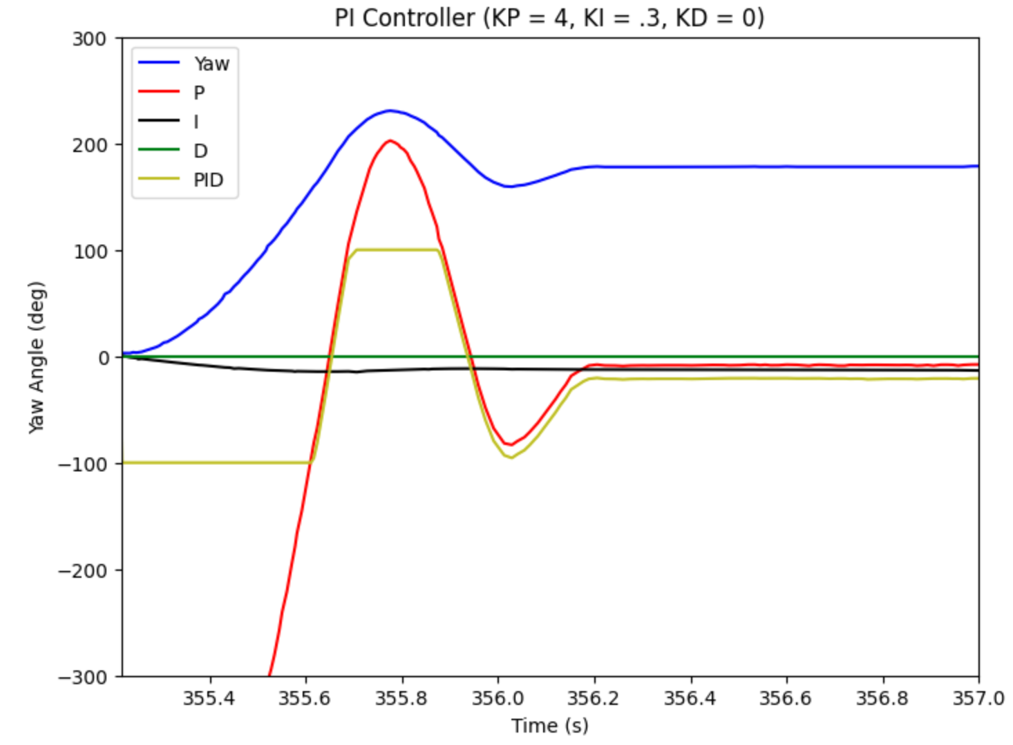
Once I was confident in my P controller, the next step was to move to the integral term. This also required some trial and error, as the integral term will add extra overshoot and decrease the rise time. However, these will also be issues that can be mitigated by implementation of the derivative gain at the end. For the orientation control, I found that a gain of 0.3 was most optimal. A video of the PI controller as well as the accompanying plot of angle, P, I, and PID over time are shown below.
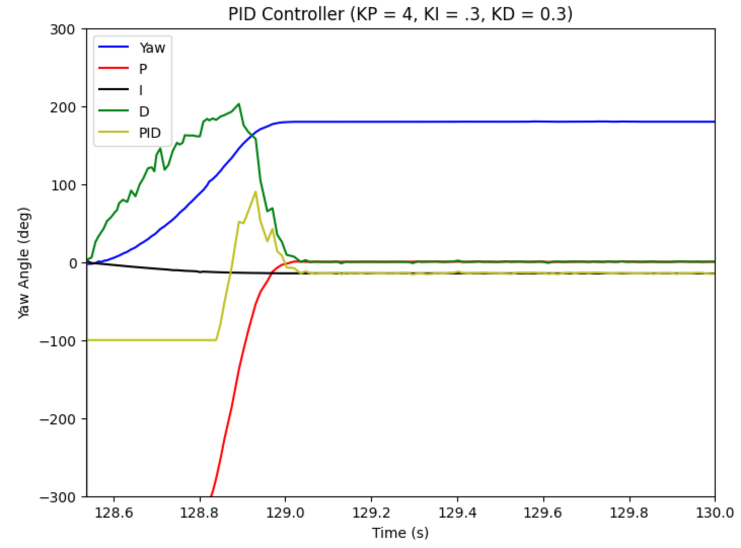
The final step was to implement the derivative gain and finalize the PID controller. I started at a relatively low value of 0.1, and after a few trials, concluded with a value of 0.3. This KD value successfully eliminated all overshoot while also decreasing the initial rise time to under half a second. A video of the PID controller as well as the accompanying plot of angle, P, I, D, and PID over time are shown below.
IMU Degrees Per Second
One issue that arose with the IMU is that my PID controller causes the RC car to correct itself too quickly. In summary, the IMU's default setting causes the degrees per second that it can handle to max out at 250 dps. However, the values of my PID gains causes the RC car to move at much faster speeds. This means we need to manually adjust the max dps that the IMU can handle. While the IMU will be able to track faster rotational speeds, it does so at the expense of precision. This might have to be continually adjusted for future labs where the precision of the angle is much more important. A snippet of the code to manually adjust the dps is shwon below.

Additional Task: Wind-Up Protection
The integral wind-up can be a huge issue. Because the motors can only range from 0-255, once the PWM signal hits 255, the system becomes saturated. The integral value might continue to rise, yet it will not impact the system. However, when the integral value goes to decrease when the RC car has overshot its desired value and the error becomes negative, it might not be able to accurately unwind due to its large built up positive error. To prevent this, I implemented a cap on the integral value. This means that when the integral component reaches +/- 100, it becomes manually set to +/- 100. This prevents the integral value from running too high or too low and messing up the rest of the system.
Lab 6 Takeaways
This lab was very useful because it provided an additional opportunity to gain experience with implementing and tuning a PID controller. This lab built nicely on top of Lab 5 to create a holistic understanding of how to adequately control the RC car and have it perform simple tasks. I can see how these two controllers in unison will allow our robot to conduct more advanced tasks in future labs.