Lab 5
The purpose of this lab is to design a PID controller for our RC car. Since I am part of the 5000 level class, I had the choice to design either a PI or PID controller for my robot. The task for this lab is to have our robot drive towards a wall and stop exactly 1 foot (304 mm) away from the wall. By altering the values for KP, KI, and KD, we can adjust the rise time, overshoot, and settling time of our controller.
Prelab
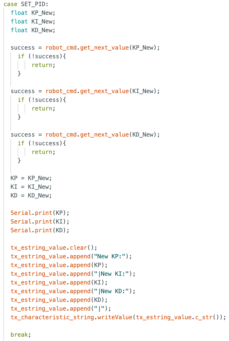
The first task of the prelab was to ensure Bluetooth was adequate in order to start and end the PID controller for the robot as well as collect data for debugging and analysis. In order to speed up testing, I also implemented cases to define the necessary controller gains (KP, KI, & KD) and the target distace (304 mm for the final test). This way, I could redefine them via bluetooth and do not need to reflash the Arduino for each small change. The Jupyter commands as well as Arduino cases for setting the PID gains as well as starting the PID controller with a target distance are shown below.
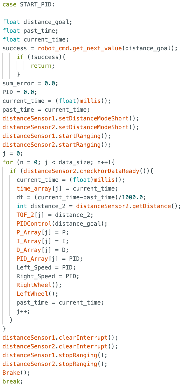


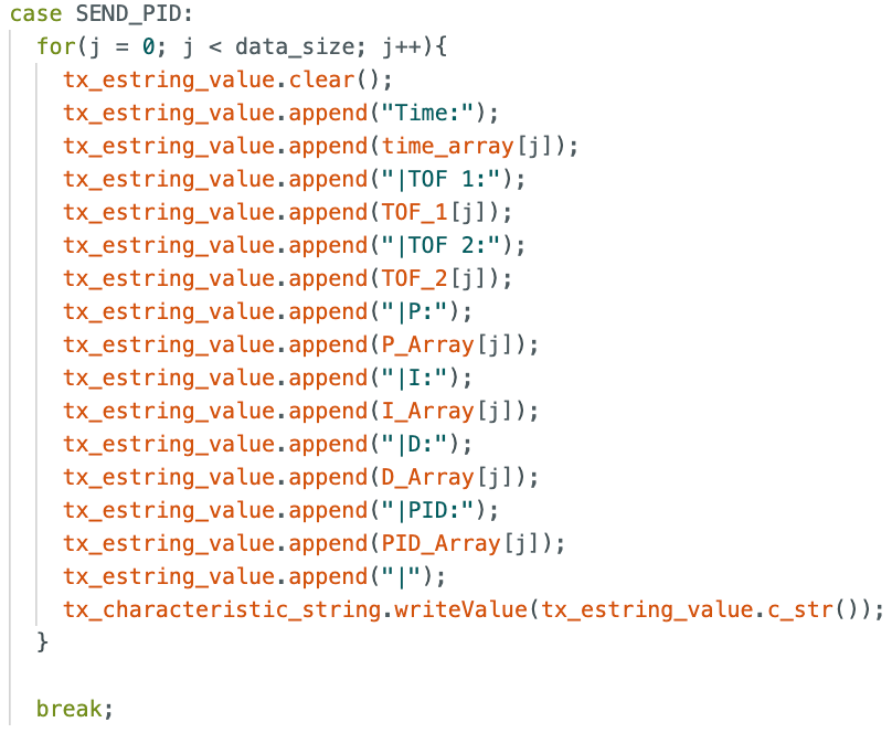
During the START_PID case, I store the time, TOF sensor reading, P value, I value, D value, and PID value in arrays. Once the test is over, these arrays can then be sent to Jupyter via bluetooth using an additional case called SEND_PID. This case is shown below. The data can then be parsed locally and plotted in Jupyter to help with debugging.
Position Control
As mentioned above, the goal of this lab is to have our robot drive as fast as possible towards a wall, and then stop when it is exactly 1 foot away from the wall. We also want this task to work in a variety of conditions such as changing floor material (carpet, tile, hardwood) or starting distance. Based on the range of PWM values for motor input and output from the TOF sensor, we can calculate a starting range for the proportional controller gain. This equation is (max PWM)/(max error), which equates to 255/4000, or 0.64. This will be a good starting spot to begin calibrating our P controller. The TOF sensor has two modes, short and long. They have different sampling rates, different ranges, and different accuracies. Therefore, it will be good to test both options to see which performs better durin this test. For starting, I will begin with short range mode.
PID Implementation
To begin, I started simple by developing just a P controller. Once the P controller works, then I will move forward with the PI and PID controller. The general equation has three components: proportional, integral, and derivative. The equation is shown below.

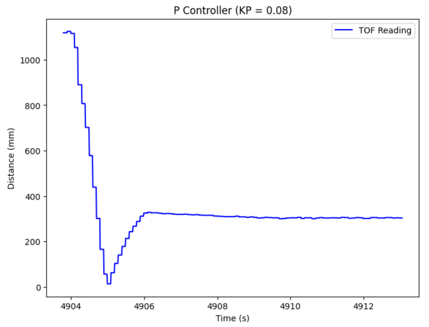
The error is found by taking the difference between the current TOF sensor reading and the desired distance. Then, this error is multiplied by the KP gain to achieve the total P controller output. This value can then be used to update the motor speeds for both the right and left motors on the car. The goal of testing the P controller is to approach the wall quickly, yet avoid too much overshoot so it does not slam into the wall. I found a good value to be 0.08. Using this method, I was able to achieve a linear speed PWM value of 166. A plot of the TOF reading over time is shown below.
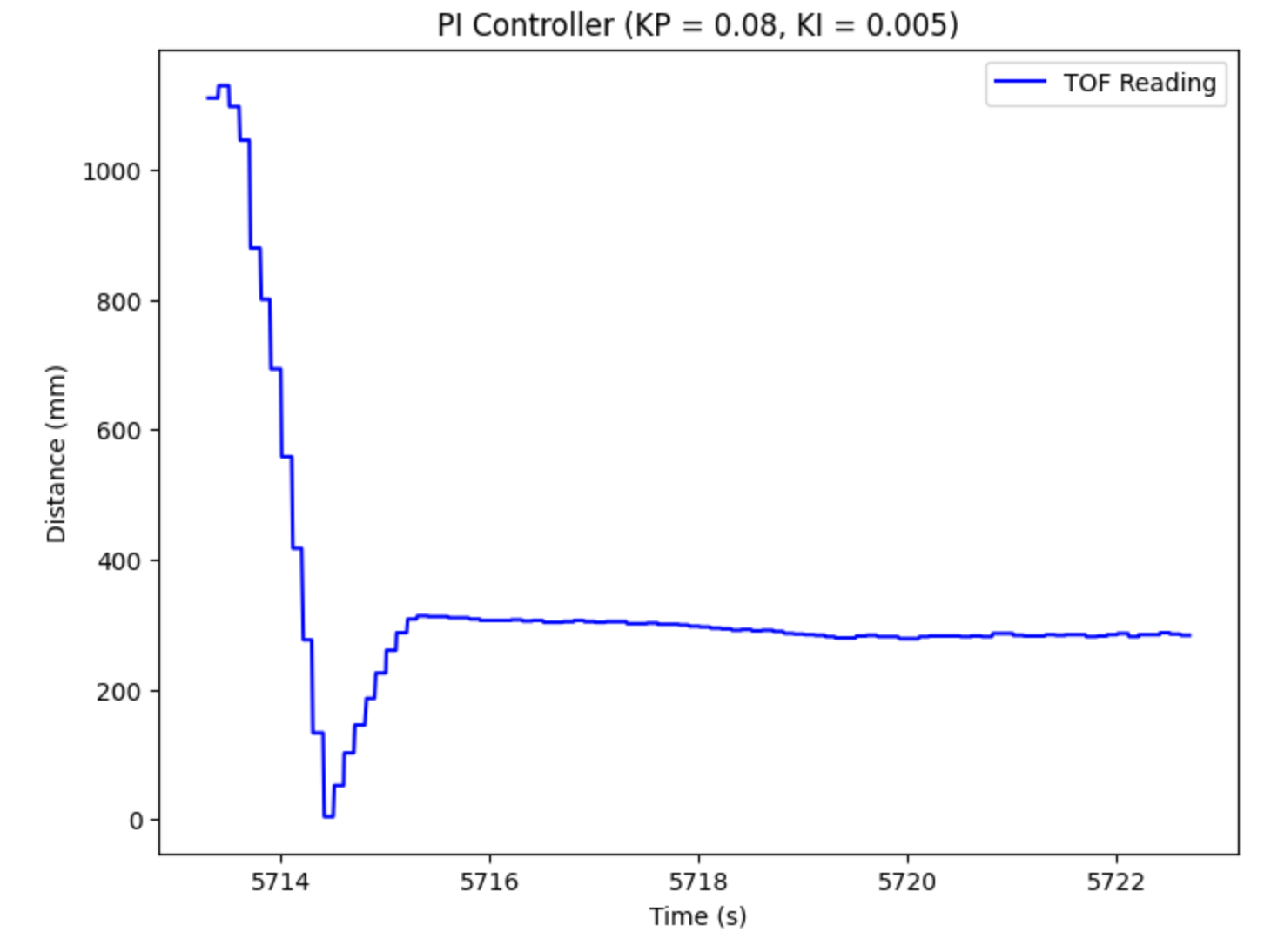
The next step is to include the integral component to make a PI controller. While we cannot calculate an integral exactly, we will take the same error as calculated in the P controller and multiply it by the change in time, dt and the gain, KI. Then, we will add this to the previous error, creating a sum of errors to find the total "area under the curve". This value will then be added to the P term that we calculated up above. However, this will lead to integrator wind-up, which could go to +/-infinity and ruin our controller. Therefore, I will cap the value at +/-100 to prevent the I value from overhwhelming the rest of the terms. I found this value experimentally through trial and error. I started my integrator gain value around 0.01, and ended uplowering it to 0.005. The goal of the I term is to decrease the steady state error, yet the higher it is, it also leads to instability with settling time and overshoot. For the PI controller, I was able to achieve a max PWM value of 170. The plot of the TOF reading over time is shown below.
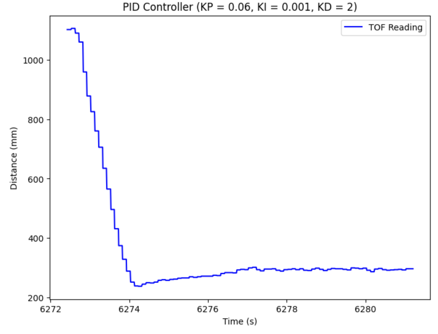
The final step is to include the derivative component and complete the PID controller. The derivative term is found by taking the difference between the current error and previous error and dividing by the change in time, dt. Then, we can multiply by our gain value, KD, to calculate the total term. Then, we add this to the P and I terms solved above to find the total PID value. The purpose of the derivative term is to decrease overshoot, yet if you make the value too high, the it increases the settling time too much. I started at 5, and ended up decreasing to 2. Also, I adjusted my KP and KI values to 0.06 and 0.001 respectively. I was able to achieve a max PWM value of 124. The plot of the TOF readings over time is shown below.
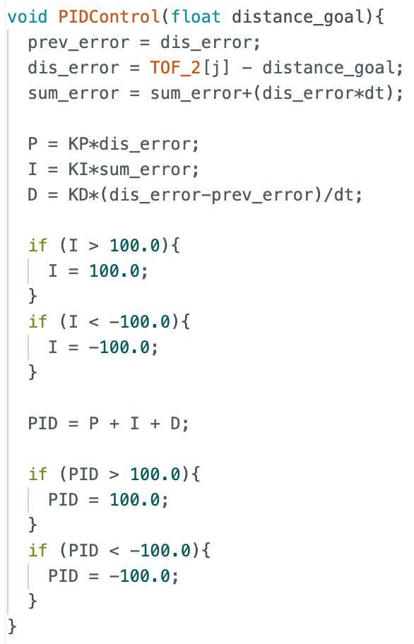
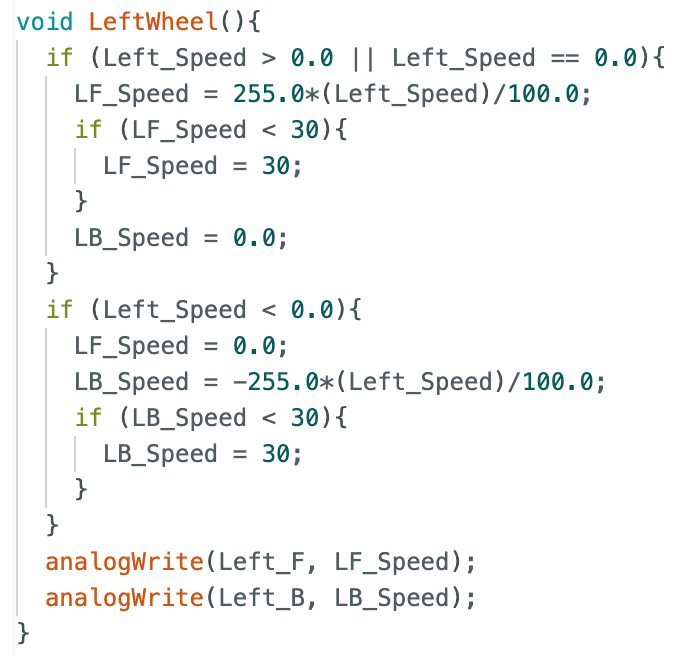
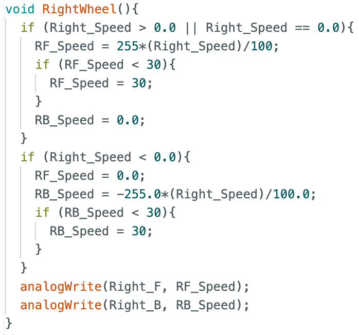
The full helper function for PID implementation is shown below. Additionally, I included the helper functions used to assign the new PWM values to my left and right motors. In these functions, I converted the +/-100 scale to the PWM +/-255 scale. Additionally, I created a lower limit of 30, which is where I found issues with the deadband.
Trial Videos
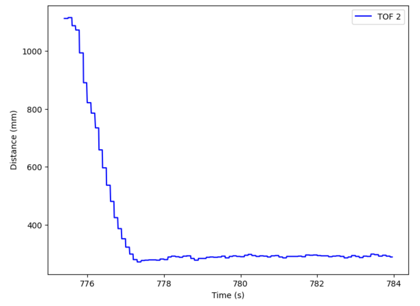
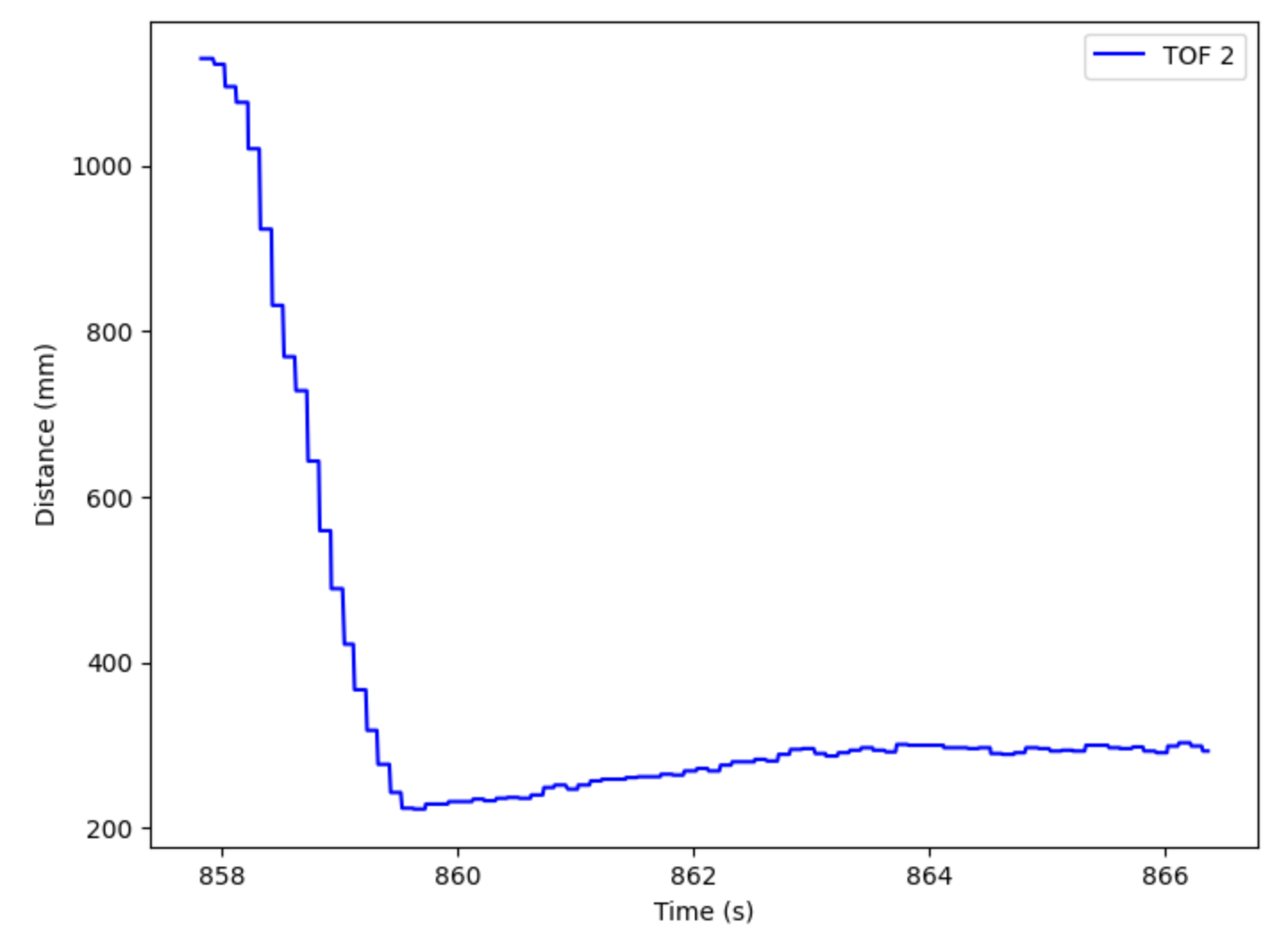
In order to validate the PID controller, I ran the wall test three times to ensure accurate and repeatable data. The three videos are shown below. In each trial, the car started about 1100 mm away from the wall (carboard box), and it finished exactly 1 foot away from the box (+/- a few mms). The three plots of TOF sensor with respect to time are also shown below.

Frequency Discussion
As found during Lab 3, my TOF sensors return data about every 100 ms. While it is relatively fast, it is still the limiting factor when it comes to our Arduino loop, which runs every 10 ms. When running the PID control regardless if the TOF sensor data is ready to be collected, I found that the PID control runs about every 8 ms. This is considerably faster than the 100 ms from the TOF sensor.
Linear Extrapolation
Linear extrapolation is implemented because the sampling frequency for the PID controller is much faster than the TOF sensors. This means that we want to estimate the distance when the TOF is not yet ready to gather new data. In order to do this, we will take the difference between the past two TOF data points and solve for the slope by dividing by the dt value. Then, we will multiply this slope by the PID sampling rate (PID_dt) to estimate the current distance from the target. This is a simple linear extrapolation algorithm that will hopefully allow or PID to be more accurate. My code demonstrating this extrapolation is shown below.

Additional Task: Wind-Up Protection
The integral wind-up can be a huge issue. Because the motors can only range from 0-255, once the PWM signal hits 255, the system becomes saturated. The integral value might continue to rise, yet it will not impact the system. However, when the integral value goes to decrease when the RC car has overshot its desired value and the error becomes negative, it might not be able to accurately unwind due to its large built up positive error. To prevent this, I implemented a cap on the integral value. This means that when the integral component reaches +/- 100, it becomes manually set to +/- 100. This prevents the integral value from running too high or too low and messing up the rest of the system.
Lab 5 Takeaways
This lab definitely had its ups and downs. While the implementation of the proportional controller is relatively straight forward, I ran into a lot of debugging challenges when moving forward with the PI and PID controllers. Additionally, there were a lot of unexpected issues, such as batteries dying and motors fatiguing that proved to be problematic while conducting the lab. However, I learned a lot about debugging and how to eliminate possibilities and hone in on the issue causing the whole system to malfunction. I found it easiest to step back and think big picture about the logic of the code. Moving forward, I will definitely seek value from this lab as the first of the many challenging labs ahead.