Lab 4
The purpose of this lab is to convert the RC car from manual to open loop control. We will be soldering motor drivers, and inserting all necessary components into the chassis of the RC car. Finally, we will use PWM signals to show that the RC car has open loop control.
Prelab
Before any soldering can be conducted, it is important to decide which pins will be used for the motor drivers. Each motor requires two pins (one for forward control and one for backward control). I chose pins 9 and 11 for the right motor and pins 12 and 13 for the left motor These were chosen by looking at the Artemis datasheet to avoid any pins that are not used for PWM control. Inside the vehicle, it is best to keep the motor drivers away from the Artemis to reduce EMI. The solder connections and pin initializations are shown in the images below. The blue wire and solder bridge are connected to the DC motor, whereas the purple wire and solder bridge are connected to two PWM pins on the Artemis. The power comes from a 650mAh battery, and the motor driver is also connected to a ground pin on the Artemis.
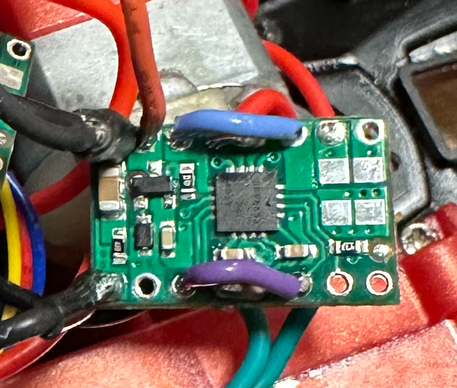
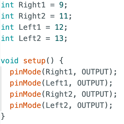
The motor drivers require more power than the artemis, so we will connect the 850mAh battery to the motor drivers and use the 650mAh battery for the Artemis. We cannot use the same battery because the large changes in current can damage the Artemis and cause issues during the open loop control.
Dual Motor Drivers (Power Supply)
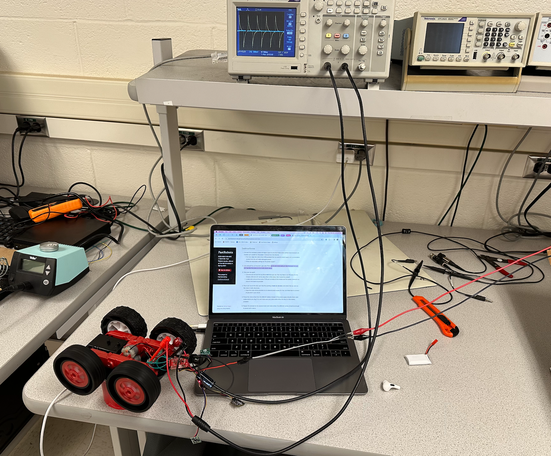
The motor drivers are first connected to the power supply, which can be more useful than using batteries. The batteries lose charge relatively quick, and the power supply will be able to supply a more consistent input voltage. The power supply was set to around 3.7 volts, which is the same voltage output as the 850mAh battery that we will use to power our motor drivers later in the lab. The setup for this is shown below.
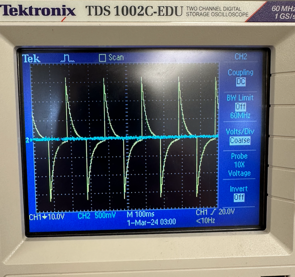
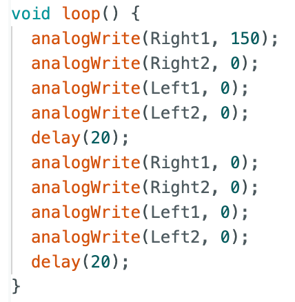
I used basic analogWrite commands to move the right and left motors separately for different trials. I tested the right motor first, setting one of its pins high at 150, and then its other pin and the two left motor pins low at 0. Then, in the loop, quickly switching the high motor pin between 150 and 0, showing a pulsing pattern on the oscilloscope. This can be seen in the image below where Channel 1, the yellow line, illustrates the voltage input based on the PWM signal. The code to run this is also shown below.
The next step is to test that both motors work. Below are two videos of the wheels working as well as the code used to test the motors. For each motor, it goes forward for two seconds, pauses for two seconds, then reverses for two seconds.
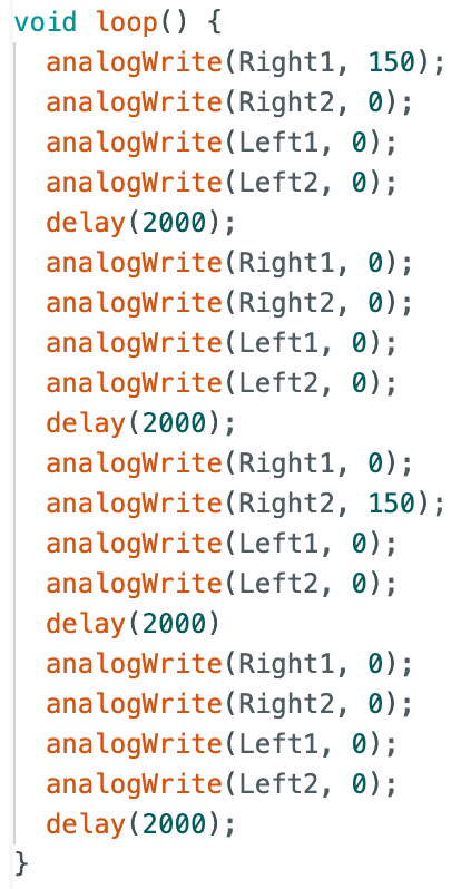
The first video is the right motor. The second is the left motor.
Dual Motor Drivers (Battery Power)
The following video shows that the RC car can run via battery power. It also demonstrates both wheels spinning at the same time.
Final Component Setup
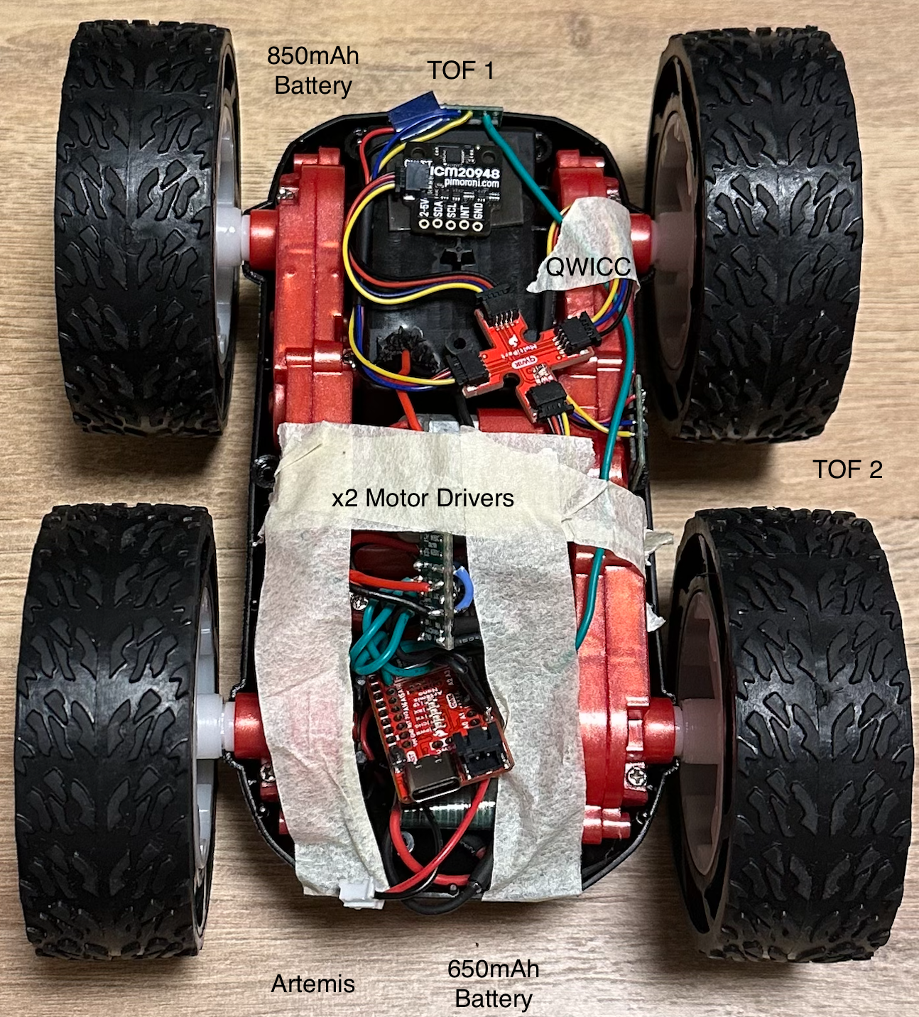
The full assembly of the RC car with the various components is shown below. The Artemis, motor drivers, and 650mAh battery are all in the main compartment below the tape. The two TOF sensors are in the front and on the right hand side. Finally, the 850mAh battery is on the underside in the original battery compartment. A majority of the wires are stranded wires; however, there are a few solid core wires that were used for short connections.
Lower Limit PWM
Through experimental testing, I found that the lower limit for PWM for both of my motors is 32 when moving forward from a standstill. This was found by starting at around 50 and slowly decrementing the PWM value. While turning, this value is much higher. For my motors, it was around 120. This was found using the same method as for moving forward. For each case, I placed a large delay in the code so I had time to place the robot on the floor prior to the motors starting. One potential issue is that the battery begins to lose power throughout testing. This means that these values could be slightly higher than the minimum when using a freshly charged battery.
Straight Line Test
In order to test the spin rates of the two motors, I conducted a straight line test using a piece of tape that was 6 feet long. A video of this is shown below. Based on the ability of the RC car to make it from one end to the other consistently without straying, I am confident that I do not need a calibration factor for my motors.
Open Loop Test
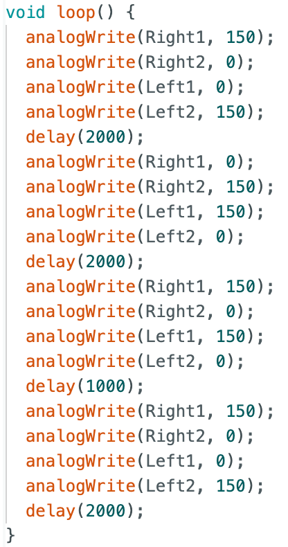
This open loop test is a first trial at complete open loop control. After assembly the full car, I set down the car and allowed it to complete a small trial. In this test, the car moved forward for two seconds, reversed for two seconds, and then rotated for one secon and proceeded forward again. The video and code for this test are shown below.
Additional Task: AnalogWrite Frequency Discussion
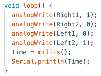
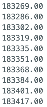
The analogWrite command on the Artemis runs at around 70 Hz. This seems a little low, but it is backed up by the time stamps printed to the Serial Monitor on the Artemis. The time stamps are shown below. We will most likely need to increase this frequency to have better and more accurate control over the robot.
Additional Task: Lower Limit PWM in Motion
As discussed earlier, the lower limit PWM from a standstill for my motors is 32. In order to find the lowest PWM value once the car is in motion, I first started the car at 32, then incremented down. Experimentally, I found this value to be 30.
Lab 4 Takeaways
This was a very fun and informative lab. It was the first time I had done a major soldering project. It will also be very important to understand how the wiring is all connected in case there are major crashes that cause things to go haywire in future labs. Overall, I look forward to being able to implement the TOF sensors and new functionality in future labs to accomplish more advanced tasks.